Pacemakers on the Electrocardiogram
Pacemakers Stimulus:
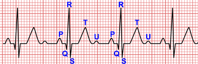
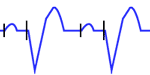
The pacemaker impulse is recognized on the electrocardiogram as a sharp, narrow spike. Its duration is generally less than 2 ms (half a small square), and it appears as a vertical line on the routine EKG. This spike is followed by a cardiac electrical activity (P wave if atrial pacing or QRS if ventricular pacing).
The International Pacemakers Code
Related article: Pacemaker nomenclature.
The combined efforts by the North American (NASPE) and British (BPEG) societies of pacing and electrophysiology have defined the international code (NBG) for the classification of the various pacing modes. The pacing modes are assigned a 5-letter code that describes their primary function.
- The first letter designates the chamber in which stimulation takes place: none (O) ventricular (V), atrial (A) or both (D).
- The second letter indicates the sensing site: none (O) ventricular (V), atrial (A) or both (D).
- The third letter defines the mode of response to sensing: inhibited (I), triggered (T), both (D) or none of these (O).
- The fourth letter indicates the presence (R) or absence (O) of rate responsiveness.
- The fifth letter is used to indicate whether multisite pacing is absent (O) or present in atria (A), ventricles (V), or any combination of A or V (D) 3.
More information: Pacemaker momenclature.
Characteristics of the Electrocardiogram of Electronic Pacemakers according to the pacing site
Normal conduction: Pacing is inhibited by sensed spontaneous cardiac depolarizations.
The normal rhythm is observed on the electrocardiogram, without pacemaker spikes. This is a normal function of the pacemaker, it is often confused with a pacemakers malfunction.
A magnet may be applied to convert the pacemaker to the fixed-rate mode (VOO or DOO), and pacing can be examined 2.
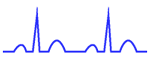
Atrial Pacing: Pacer spikes are followed by P waves whose waveform is different from sinus P waves.
P waves are followed by normal QRS complexes (narrow QRS except alterations).
Ventricular Pacing:
The pacer impulse is followed by an abnormal QRS complex, the characteristics of which usually give a fairly good indication of the location of the stimulating electrode 1.
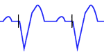
Right ventricular pacing: QRS complexes are similar to those of complete left bundle branch block.
In many patients, with a typical complete LBBB pattern in the limb leads and right precordial leads there is a predominant negative deflection in leads V5 and V6.
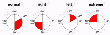
In most cases of ventricular pacing, the tip of the electrode is located at the apex of the right ventricle. The apex-to-base sequence of depolarization results in negative QRS complexes in inferior leads II, III, and aVF.
If the site of stimulation is at the inflow or outflow tract of the right ventricle, the frontal plane QRS axis is usually normal.
If the site is located immediately below the pulmonary valve, the QRS axis becomes vertical or even rightward.
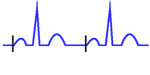
Dual-chamber pacing: There are two pacer spikes, atrial spike followed by a P wave, and ventricular spike followed by QRS complex similar to complete left bundle branch block.
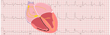
Biventricular pacing (ventricular resynchronization): Ventricular resynchronization with biventricular pacing has become an established therapy for patients with left ventricle dysfunction in the presence of ventricular asynchrony due to intraventricular conduction disturbances.
The paced QRS complex is often less wide than the QRS complex caused by single-chamber pacing. QRS complex is often positive in lead V1 when the right ventricle is paced from the apex.